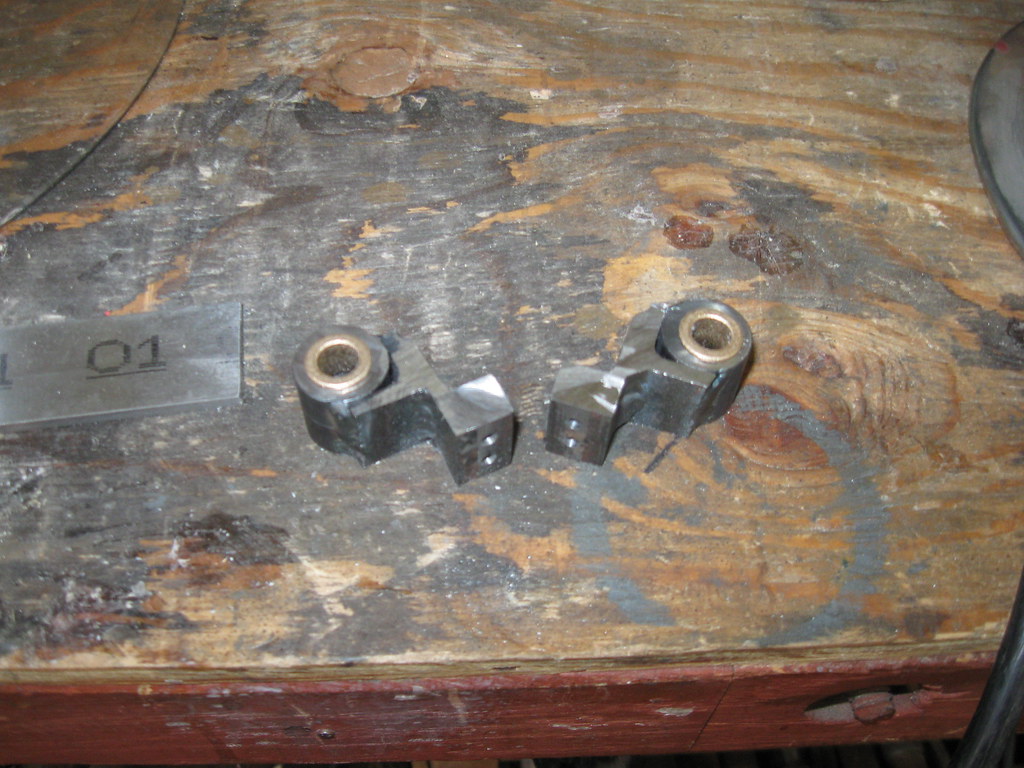
I built up the brackets that attach the screw to the lathe bed first. They are composed of a piece of 1/4" square steel, that buts against the lathe bed, on top of which is stacked a piece of 1/8" thick, 3/4" wide steel sheet, on top of which is stacked a piece of 3/4" x 3/4" angle iron, 1/8" thick, and in the angle sits the actual bearing holder. I welded all that together. The bearing holder is a piece of roughly 3/4" steel cylinder, about 2" long, that I turned and marked a halfway point, then center-drilled on the lathe with a 1/4" hole going all the way through. At that point I welded the whole works up. There's a reason for this sequence: I need the axis of the cylinder to be precisely parallel to the face of the 1/4" square, which bolts to the lathe bed, because if it isn't, the screw won't be parallel to the bed. Since the screw is held on both ends, it would be held in a curve, which would be *extremely* difficult to turn. I bored the 1/4" hole before welding everything up so I wouldn't have to work as much in the counter-boring step, which is a tense step.
I'll start with a shot of the brackets, already welded, cut, and with the bearings pressed in, because that way the construction is the most obvious.
Here's the shot where I was counterboring that.
Be *extremely* careful when you're turning big off-center stuff on your lathe. Use a low setting and feed the boring bar in slowly. I have a thin sheet of aluminum over the ways in hopes it would take all the damage if something touched, because there's only a few millimeters of clearance between the angle plate and the ways. Make sure the boring bar is extended far enough that it can make it all the way through the bracket, and make sure that when it is all the way through the bracket, you don't have any conflicts between that angle plate and the carriage. Unlock the drive and spin the spindle by hand throughout the range you're going to be working, to make sure there aren't any crashes. It wouldn't hurt to clamp a carriage stop on the ways to prevent disasters. I thought I could counterbore maybe halfway through and then use a drill, and it would be guided by the existing counterbore, meaning I didn't have to bore all the way through. It appears I was wrong: one bracket seems to be slightly angled with respect to the bed, so there's some friction on the leadscrew as mounted. Oh well.
To sum up: I cut the bearing holder, center-drilled it to a smaller diameter than I needed, built up the bracket, welded up the bracket, bored it, then cut it in half, so I had two identical brackets, one for each end, then pressed in bronze bushings, and mounted it to the lathe bed.
Two shots of the leadscrew bracket bolted to the bed:
From the headstock end.
And from the tailstock end, a very blurry shot because I'm an incompetent photographer(but at least you can see the bronze bushing):
Here's the feedscrew attached to the lathe.
An aside on location. I wanted the feedscrew to be high enough to interface easily with the bottom of the carriage. I wanted it to be low enough to clear a 64-tooth gear on the leadscrew. I wanted it to be as close as possible to the lathe to minimize the torque on the brackets. That dictated the design of the bracket (that and it matched some of my scrap.)
I cut the Acme leadscrew down to 0.3125" in diameter, because that was the closest standard dimension for a bronze bushing, that involved cutting away all the screwform on the leadscrew. I would've preferred to cut it to 0.375" but there was still 0.010" or so of the root of the screw showing, and that's just not done. This is why Atlas went with the much shorter-depth stub-thread form on the leadscrew: so they didn't have to cut away as much steel to make the journals on the ends of the screw.
To attach the carriage to the fixed nut, I made a small off-center bracket that wraps around the nut and attaches to it with two screws, one through each side. This hangs downwards because of gravity, but can flip up to engage a pair of wings I've attached to the bottom of the carriage.
The carriage bracket was made out of a piece of 3/4" x 3/4" angle bracket, 1/8" thick, that I ground back a bit to fit what I needed. I cut a slightly trapezoidal notch in it, and drilled and tapped the carriage to attach it. I then carefully ground away the area behind the notch until the nut, when rotated upwards into the latch position, just touched the bracket as it rotated into position, deflecting the feedscrew slightly downwards. The combination of the trapezoidal shape and the contact with the bracket keep the nut in position when the feedscrew is turning. (Unfortunately, using a right-hand acme thread means it tends to want to disengage as I'm feeding towards the headstock. However, it thus far hasn't moved during use, so I think it's okay. If it's not I'll either add a small supermagnet or a latching mechanism.)
Here's the view of the carriage bracket from the under/backside of the carriage:
And here's a shot from the frontside:
(I'm not sure that's actually a useful shot.)
Now a few shots of the carriage on the lathe, with the nut engaged and disengaged.
Nut unlocked:
Nut locked:
Angled shots for better perspective.
Nut unlocked:
Nut locked:
And finally, the lathe all put back together, with the lead and feed screws both installed:
This page written 15-Jan-2011, last modified 23 May 2023
Back to the Atlas 618 main page