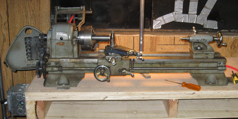
The 618 was made by the Atlas Lathe company, and rebadged and sold by Sears as the Craftsman 101-series lathe from roughly 1930 to the 1980's, in various versions. Details about the history can be found at Tony's UK Lathe web page.
An enormous trove of material focussing on the 618 exists at janellestudio.com. I am going to attempt to summarize some of this in a short form, on this page. There is also a wealth of information on the Yahoo! Craftsman 618 Users Group, which is active with maybe an average of a message a day and all the old messages saved in an archive, which serves as the basis for the sorted-by-topic janellestudio collection.
The 618 was built with plain bronze bearings in earlier versions, or Timkin roller bearings from the 1950's onwards. The bronze version was known as 101.07301, and the Timkin version as 101.21400; both were also available under other Sears numbers but those are the ones most commonly seen and referred to. The bronze bearing version seems to have a better finish cut, while the Timkin version can run at higher speeds. Both bearings are still commercially available. The Timkin bearing numbers are: two 07196 cups, one 07079 bearing and one 07100 bearing.
Resist the urge to replace the bearings: it's a difficult job and spending the time to try and salvage your current bearing set is probably a better idea.
Very early versions of the lathe had a 1" x 8 tpi spindle nose, while most later versions had a 1" x 10tpi spindle nose. There are a lot of woodworking chucks available in the 8tpi size, few of which seem to be hefty enough for metalworking. There are very few commercially available chucks with the 1x10 threading, but there are places that provide chuck adapter plates with this threading, including ebay, for a reasonable price. The best supplier I've found is Little Machine Shop, who provide parts specifically for the 618, including a lathe chuck adapter plates.
Some new old stock parts for the lathe are still available from both the Sears parts department and Clausing Lathe. Some are quite reasonably priced. Ebay always has lots of parts. The 'buy it now' parts are often comparable in price with the parts bought directly from Clausing.
Some aftermarket mods are available from , including quick-change toolposts. More aftermarket mods are available from Bower Machine including a replacement cross-slide with t-slots.
Ebay seller Metal Magic apparently makes custom parts for the 618, including such difficult-to-replace parts as the 16/32 stud gear.
The gearing that originally came with the lathe are 1/2" wide Zamak gears, 14 1/2 pressure angle, 24 pitch, with 1/2" bores with dual keyways. These are identical to the Sears 109 metal lathe gearing, the only parts that are shared with the 109. None of the other Atlas/Clausing lathes use these gears. The original gearset that came with the lathe included 20, 24, two 32, 36, 40, 44, 46, 48, 52, 54, 56, and two 64 tooth gears. Boston Gear makes gears that will work with the lathe, but they have to be faced to the right hub thickness (about 0.378") and broached with a double keyway pattern.
The leadscrew is a 1/2" x 16 tpi Acme Stub Thread. A suitable Acme Stub thread cutting tool is available from Wholesale Tool, among other places, although used leadscrews are commonly available on ebay. The half-nuts are Zamak. It is fairly easy to remove the halfnut carrier assembly from the carriage (remove tailstock and rear leadscrew bearing, slide carriage off bed, remove bolts on either side of the halfnut lever. The halfnut lever is just pressed lightly onto the shaft: pull it off. Then you can remove the halfnut clamping assembly from the carriage and work on it.) The halfnuts are still available from Clausing, and sell on ebay inexpensively. It's worth it to remove this and clean out the halfnut threads with a brass brush every now and again. If you do buy halfnuts, try to get ones that come with the bracket in which they slide, since there are different versions of this assembly. I've read that there are also two different specifications for the Acme thread on the leadscrew, but have never managed to confirm this.
The bed is flat with the carriage running on the outer portion of the ways, and the tailstock running on the inner portion. Like most lathes, the 618 will show wear in the bed immediately adjacent to the headstock. The carriage will move much more easily in this area. A flat bed is easily and cheaply reground by a machine shop, but there are problems with this: the carriage traverse will no longer mesh correctly with the rack on the underside of the bed, requiring the rack to be removed and shimmed downwards, the leadscrew will require slight vertical adjustment, and the carriage gibs will require shims. This is more work than it sounds.
A conventional setup has the motor sitting behind the headstock and a cammed layshaft with pulleys between the motor and the headstock, with a two-speed pulley on the motor and one end of the layshaft, and a four-speed pulley on the other end of the layshaft and the headstock between the headstock bearings. The pulleys are designed for 3L v-belts. Because of the location of the headstock pulley, removal of the headstock shaft is required to replace the v-belt, and this is not a task for the nervous: it requires driving the spindle out of pressed bearings. I strongly recommend buying Fenner twist-lok v-belts, because they can be broken and threaded through the headstock without removal. They seem to work very well.
Some newer 618's used plastic gibs on the cross and compound slides. Many users think these are objectionably flexible and replace them with steel or brass gibs, which are available on ebay and aren't too difficult to fabricate.
Model limitations, eccentricities, and issues:
The MT1 tailstock is barely adequate. Heavy or intermittent cuts with a live center will result in visible deflection of the live center. If you can use a dead center with minimal tailstock extension this helps. The compound slide is considered weak by some people, particularly if at full extension under heavy loading. If you're making your own t-bolt to fit in the compound t-slot make it with very generous flanges. People have been known to shatter the cast iron t-slot flanges by using a hex bolt as a t-bolt and tightening it heavily.
The compound slide use standard 60 degree threads rather than acme: it's just a 1/4" x 20tpi thread. The cross-slide uses a 1/4" x 10tpi acme. They have very small thimbles, and the thimbles transfer force from the handle to the body of the slide, which means it is very difficult to reset them during use.
The headstock is somewhat complicated. There are many setscrews in components on the headstock but not all should be tightened. The outboard-most component is a collar that sets the headstock bearing tightness. With the lathe warm (having run for like an hour) this collar should be tightened until there is no perceptible play in the headstock (measured by putting a piece of stock in the chuck and wiggling on that, feeling for a clunk) and then tightened another half a turn. This collar has a setscrew that bears against the threads of the spindle. Ideally, you should have a piece of lead shot in the hole between the spindle and the setscrew end. A small bit of copper clipped from the end of a 14 gauge piece of interior wiring would also work. I found it much easier to adjust the headstock bearing tightness by making a wrench that clamps onto this collar. Adjacent to the bearing tightness collar is the spindle gear, and then a collar and the dust cover for the outer bearing.
The spindle between the headstock bearings has three components: a bushing, the pulley, and the bullgear. The pulley is basically free-floating. It is held in place by the outboard bushing and the bullgear. The bushing has a setscrew that bears against the spindle, which should be tight. The pulley has a setscrew that does *not* bear against the bushing: it serves merely to fill the hole for the pulley lubrication. It *can* be tightened down against the spindle, but this is neither necessary nor desirable since it makes the backgearing not work. The bullgear has two setscrews, one on each side. One bears down on the spindle and holds the bullgear against the inboard side of the pulley. This should be tight. The other setscrew presses on a spring-and-ball detent that locates a plunger on the inboard face of the bullgear. This plunger attaches the pulley to the bullgear for direct drive of the spindle. If the spring and ball are still in place, the plunger setscrew should not need to be adjusted. There is also a setscrew on the backgear shaft, between the two gears. Like the pulley, this is only provided to cover the oiling hole for lubricating the backgear, and should not be tightened.
The main bearings have oil cups on the top of the headstock. On Timkin-bearing-equipped models, the right bearing seems to empty many times faster than the left one. Check and fill the inboard bearing cup at least every time the machine runs, and possibly every couple of hours during extended continuous operation. On my lathe, the left one never dropped at all so finally I dug down into the bottom of the cup with a toothpick and moved the wick around and now it does drain slowly, so it's possible it had gotten plugged with debris.
As I fabricate accessories I find useful I'll document them here.
Right now this consists of a line boring setup, but I've also made a spherical turning setup, a tangential cutter holder, and a tubing holder so that the line boring setup can be used to fishmouth tubing for brazing.
Some other modifications for 618 lathes
This page written 12-14 Jan 2010, last modified 2023 05 273